Add to Favorites |
 Worldwide
 中文 |
Polski | English
中文 |
Polski | English


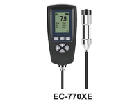
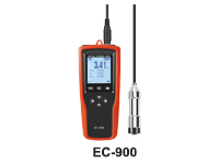
A coating thickness gauge (also referred to as a paint meter) is used to measure dry film thickness. Dry film thickness is probably the most critical measurement in the coatings industry because of its impact on the coating process, quality and cost. Dry film thickness measurements can be used to evaluate a coating’s expected life, the product’s appearance and performance, and ensure compliance with a host of International Standards.
Dry film thickness (DFT) can be measured using two methods: destructive thickness measurement, where the coating is cut to the substrate using a cutter; and non-destructive coating thickness measurement, using techniques which do not damage the coating or the substrate such as magnetic, magnetic induction and eddy current thickness measurement methods.
The non-destructive coating thickness measurements can be taken on either magnetic steel surfaces or non-magnetic metal surfaces such as stainless steel or aluminium. Digital coating thickness gauges are ideal to measure coating thickness on metallic substrates. Electromagnetic induction is used for non-magnetic coatings on ferrous substrates such as steel, whilst the eddy current principle is used for non-conductive coatings on non-ferrous metal substrates.
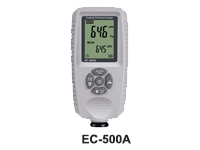
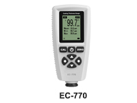
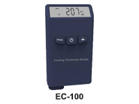
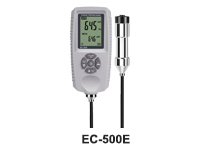
Coating Thickness Gauges
WELLZiON.com offers a wide range of coating thickness gauges to measure dry film thickness.
The WELLZiON range of non-destructive coating thickness gauges are series of digital coating thickness gauges, suitable for dry film testing, complete with a wide range of probes and calibration foils to suit your application.
 |
 |
 |
 |
 |
 |
How does a Coating Thickness Gauge work?
Dry film thickness can be measured on either magnetic steel surfaces or non-magnetic metal surfaces such as stainless steel or aluminium using a digital coating thickness gauge. The principle of electromagnetic induction is used for non-magnetic coatings on magnetic substrates such as steel. The eddy current principle is used for non-conductive coatings on non-ferrous metals substrates.
What does "accuracy" mean?
The basic measure of a coating thickness gauge's performance is the accuracy with which the gauge takes readings. That is the difference between the reading and the true coating thickness.
How to test a Coating Thickness Gauge for accuracy
In order to test the accuracy of a particular gauge it is important to have traceable coating thickness standards. With the gauge adjusted to zero on an uncoated smooth substrate and set to a known thickness standard at or near to the maximum thickness, intermediate thickness standards are measured and the readings compared to the actual thickness of the standard. The errors are the differences between the values of the reading and the value of the standard. These are most conveniently expressed as a percentage of the reading.
The importance of Coating Thickness Gauge Calibration
Calibration is the process whereby manufacturers of a coating thickness gauge sets-up, during manufacture, to ensure that the gauge meets the required accuracy specification. The procedure normally requires the coating thickness gauge to be set to known values of thickness and checked on intermediate thickness values. In modern electronic instruments the values at key points across the coating thickness range are stored as reference points in the memory of the gauge.
Why you need to Calibrate a Coating Thickness Gauge before testing?
Calibration of coating thickness gauges will be affected by the type of material, the shape and the surface finish of the metal substrate to be tested. For example the magnetic properties of steel alloys vary and the conductivity of different aluminium alloys and different non-ferrous metals, copper, brass, stainless steel etc. also vary. These variations can affect the linearity of a coating thickness gauge. This means that a gauge set-up on mild steel for example will read a different value for the same thickness coating on high carbon steel. Similar linearity effects are seen on thin or curved substrates and particularly on profiled substrates such as blast cleaned steel used for structural steelworks.
To overcome these effects most coating thickness gauges have features that allow you to set the gauge to the work being carried out, thus maximising the accuracy of the readings.
Adjusting a Coating Thickness Gauge
Adjustment is the technique whereby you can set-up the coating thickness gauge for the conditions prevailing for the work in hand. In addition to material differences, shape and surface finish the adjustment may be carried out at an elevated temperature or in the presence of a stray magnetic field. By adjusting the coating thickness gauge to these prevailing conditions the resulting errors are greatly reduced and even eliminated.
The effect of surface roughness, particularly that produced by deliberately profiling the substrate by blast cleaning with either grit or shot or by mechanical cleaning, is quite significant, to find out more click here.
Using Coating Thickness Standard to Calibrate a Coating Thickness Gauge
There are two basic types of coating thickness standard, foils and pre-coated metal. For more information on coating thickness standards for coating thickness gauges click here.
An Oscilloscope is an instrument that is used as a graph displaying device of an electrical signal. The graph will show how signals change over time. The vertical (Y) axis represents voltage and the horizontal (X) axis represents time. The horizontal sweeps at a constant rate. The (Z) axis, although not that common, can display brightness or intensity of the display. With a proper transducer, an oscilloscope can measure just about anything. A transducer is a device that creates an electrical signal in response to physical stimuli such as sound, pressure, light, heat, etc.
When graphing a signal, what do you want to find out?
The time and voltage value of a signal
The frequency of an oscillating signal
How much of a signal is direct current (DC) or alternating current (AC)
How much of the signal is noise and if the noise is changing over time
To see the “moving parts” of a circuit represented by the signal
To tell if a malfunctioning component is distracting the signal
Oscilloscopes come in many different versions(view the details at www.wellzion.com)
Analog
Digital
Mixed signal
Portable
PC based versions
If the recording of a waveform is required, a digital scope will be applicable. If you need to see the waveform in real time, or to see the original intensity an analog scope would better suit that requirement. The higher the input signal frequency is, the higher the bandwidth that will be required. If you do not have the appropriate amount of bandwidth, you risk the possibility of not getting accurate results.
If there is doubt about the amount of bandwidth that is required, then you should go the next step up. The bandwidth can usually be calculated by this formula: BANDWIDTH = (0.35 / rise time of the signal)
The higher the sampling rate, the more accurate and precise the captured waveform is. As the sampling rate increases, it allows for more samples a captured waveform has, for any given period of time.
In almost every electric application, including lab use, research and development, and product development there is a need for an oscilloscope to provide waveform analysis.
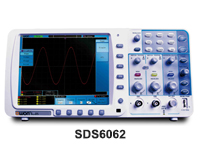
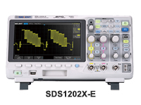
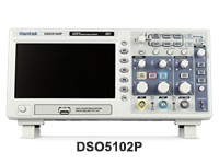
Digital Oscilloscopes (DSO)
An oscilloscope is a test and measurement instrument used primarily to measure voltage over time. A Digital Storage Oscilloscope (also known as a DSO) takes the input signal and converts it from an analog wave to a series of digital signals. Once it is digitized, the digital storage oscilloscope can then store the information in memory and display it on the screen. The faster the signal is processed, the better the display will be.
The digital oscilloscope uses graphical grid called a graticule to display a signal. The Y-axis (vertical) is usually the voltage (though it could also be current, pressure, or another type of signal that is then converted into voltage). The X-axis (horizontal) is usually time (though it could also be frequency). Some digital storage oscilloscopes also use signal brightness as their Z-axis.
To make it easier to read the graticule, it is typically broken into 8 squares (or divisions) going vertically and 10 squares (or divisions) going horizontally. This can change from manufacturer to manufacturer, but it is fairly standard. The reason why it is done this way is that as long as you know what each division is, it makes it easier to read the values on screen. Luckily, digital storage oscilloscopes can also display the exact value at a given point on the screen. You have to move your marker, or cursor, to the spot in question and you should be able to see the specific value. A scope with multiple cursors will allow you to measure the difference between to spots, which can be very handy.
Some common measurements digital storage oscilloscopes are used for include
Looking at the shape of a signal (also known as a waveform)
Checking the amplitude (strength) of a signal
Checking the frequency (timing) of a signal
Checking the amount of time between events
Looking for problems (noise) with a signal
What are the key specifications in selecting a digital storage oscilloscope?
There are typically four parameters that should be considered when choosing your instrument:
Bandwidth
Sample Rate
Rise Time
Recording Length
How much scope bandwidth do I need?
The amount of times a signal repeats itself in one second (Hertz or Hz) is its frequency. Oscilloscopes can view signals occurring anywhere from 1Hz (or less) up to 1GHz (1,000,000,000 (that's one billion) times per second) or more. Select an digital storage oscilloscope that can see more than the fastest signal you want to measure. In theory, you want your signal to be no faster than 71% of your maximum. The rule of thumb is that the bandwidth be five times (5x) greater than the maximum signal. So, if your signals to be observed are a maximum of 100MHz (100,000,000 times per second) then choose a model with a 500 MHz bandwidth.
How much sampling do I need?
As mentioned, a digital storage oscilloscope converts an analog signal into a digital one. This is done through a process known as sampling. The faster the sample rate, the more information about the original signal is captured and converted. This a common specification you see on data sheets for these types of scopes. It is measured in Samples per Second (S/s). For high-speed samples, you will often see it measured in MS/s (Mega Samples per second) or GS/s (Giga Samples per second).
There is something called Nyquist's Theorem, which states that in order to properly slice up an analog signal (so you have enough information to recreate it back again) you need to have a sample rate at least twice the fastest signal you are looking at. That is of course, a minimum amount. In practice, most scopes are built to sample at least 5 times the highest speed it can capture. So, for example, a 200MHz signal would be best sampled at a rate of at least 1GS/s.
How fast does a scope need to be?
The speed at which a signal goes from 10% of its level (in amplitude) to 90% of its top value is called the rise time. In order to see the maximum amount of each signal edge (vertical) both the scope and the probe must have a fast enough rise time. This is especially true for when the signal changes. Once again, the practical scenario calls for the rise time on the instrument to be five times faster than the signal. If your fastest signal has a rise time of 5 usec (micro second), then you want a scope/probe combo to have a rise time of 1 usec.
How deep should the memory be?
The last major specification to be considered is memory depth or record length. The major benefit of the digital storage oscilloscope is the storage part. This gives you the ability to recall, compare, and perform math functions on a captured signal. The record length is measured in samples or points. The total amount of time you can record for is determined by the number of points available and the sample rate (each sample being a point). You would simply divide the number points by the sample rate to get your acquistion time. If you have a total memory depth of 1 Mpoints and a sample rate of 250 MS/second, then you can record a signal that is 4 msec (millisecond) long.
What other factors should be considered when purchasing a digital storage oscilloscope?
Beyond the basic four specifications, it is common to consider:
Number of channels (typically two or four). If you need to record multiple high-speed signals beyond four, you might want to look at a dedicated recorder.
Size of the display is often a consideration. Larger, clearer screens make it easier to see multiple signals at once. Luckily today's digital storage oscilloscope also has different color lines for each signal.
How you capture a signal is also important. This is where triggers come into play. It is often important to see only signals with specific characteristics among the many captured. With most digital storage oscilloscopes, a variety of different trigger types are available to find particular events that happen during signal analysis.
If you are looking at packets of serial data, you may also find it useful to decode the signal to make sure that the correct instructions are being sent. Protocols such as I2C, SPI, CAN, LIN, and RS232 are commonly used to communicate between devices. It is important to make sure that the right commands are communicated when a specific event happens.
When graphing a signal, what do you want to find out?
The time and voltage value of a signal
The frequency of an oscillating signal
How much of a signal is direct current (DC) or alternating current (AC)
How much of the signal is noise and if the noise is changing over time
To see the “moving parts” of a circuit represented by the signal
To tell if a malfunctioning component is distracting the signal
Oscilloscopes come in many different versions (visit the respective sections of the WELLZiON website)
Digital
Analog
Mixed signal
Portable
PC based versions
If the recording of a waveform is required, a digital scope will be applicable. If you need to see the waveform in real time, or to see the original intensity an analog scope would better suit that requirement. The higher the input signal frequency is, the higher the bandwidth that will be required. If you do not have the appropriate amount of bandwidth, you risk the possibility of not getting accurate results.
If there is doubt about the amount of bandwidth that is required, then you should go the next step up. The bandwidth can usually be calculated by this formula: BANDWIDTH = (0.35 / rise time of the signal)
The higher the sampling rate, the more accurate and precise the captured waveform is. As the sampling rate increases, it allows for more samples a captured waveform has, for any given period of time.
In almost every electric application, including lab use, research and development, and product development there is a need for an oscilloscope to provide waveform analysis.
 |
 |
 |
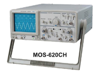
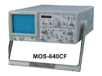
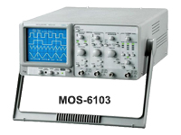
Analog Oscilloscopes
An Analog Oscilloscope will draw waveforms on its display by deflecting an electron beam that sweeps across its screen horizontally. The beam is vertically deflected in proportion to the applied voltage, which allows the shape to reproduce the shape of the target trace. Analog equipment works with continuous variable voltages. Analog oscilloscopes can display signals as they happen.
The immediate representation of a waveform on the CRT (panel) display results in a faster update rate. The CRT’s have a higher resolution and faster waveform update rate. The analog oscilloscope displays the signal in real-time with less risk of modifying any part of the original signal. The original intensity of the waveform can be observed with the CRT. Depending upon application, the intensity of the waveform can be critical.
Analog oscilloscopes are sometimes preferred by some users. They can both interpolate and aliasing the points between the waveforms. Although the analog oscilloscopes do not allow for digital storage and analysis, pre or post triggering information, and high frequency limitations, they can still be used.
The basic difference between the digital and analog oscilloscopes is the display signals. The digital scope can display signals that may happen only once and analog scopes can display signals as they happen, or in real-time.
To use an analog oscilloscope, there are three basic settings to adjust an incoming signal
Time base: Set the amount of time per division represented on the screen.
Triggering: Use a trigger level to stabilize a repeating signal, or trigger one event.
Attenuation: Adjust the amplitude of the signal before it is applied.
What is trace storage?
Trace storage allows for direct-view storage CRT’s. It will display a trace pattern that would normally disappear in seconds to stay on the screen for several minutes.
 |
 |
 |
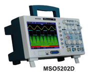
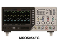
Mixed Signal Oscilloscopes (MSO)
Mixed Signal Oscilloscopes (MSO) can capture both analog and digital signals at once. A mixed signal scope usually combines 2 or 4 analog channels with either 8 or 16 digital ones. This is useful when looking at logic signals after a specific input has occurred when developing a system that combines physical input and computer controls.
There are both digital and analog channels that provide the ability to accurately time-correlate both signals. The measurements are compiled by using a single time base on a single display. Any combination of these measurements can be used to trigger the scope.
The key advantage of the MSO is that only one unit is required for conducting tests that you would normally need two units for.
An oscilloscope is a test and measurement instrument used primarily to measure voltage over time. The input signal is converted from an analog wave to a series of digital signals. Once it is digitized, oscilloscope can then store the information in memory and display it on the screen. The faster the signal is processed, the better the display will be.
Refer to the above general and digital oscilloscopes discussions that cover the common features of an MSO with a DSO.
 |
 |
 |
Applications for Mixed Signal Oscilloscopes
Aerospace
Defence
Industrial Electronics
Communications
Research and Development
The MSO treats the oscilloscope and logic channels in different ways
Logic Channels: These channels are converted to digital format, where no analog information is shown
Oscilloscope Channels: These channels use an analog to digital converter to allow the analog input to show in digital format
MSO scope vs. Logic Analyzer factors to consider
State Analysis
MSO- Yes. Separate channels for clocks
Logic Analyzer- No. No provision for clock input
Triggering
MSO- Single events on both the analog and digital channels
Logic Analyzer- Advanced sequential capabilities
Channel Count
MSO- 16 / 32
Logic Analyzer
Timing Analysis
MSO- Yes
Logic Analyzer- Yes
What other factors should be considered when purchasing a mixed signal oscilloscope?
Beyond the basic four specifications, it is common to consider:
Number of analog channels (typically two or four). If you need to record multiple high-speed signals beyond four, you might want to look at a dedicated recorder.
Number of digital channels, usually 8 or 16
Size of the display is often a consideration. Larger, clearer screens make it easier to see multiple signals at once. Luckily today's digital storage oscilloscope also has different color lines for each signal.
How you capture a signal is also important. This is where triggers come into play. It is often important to see only signals with specific characteristics among the many captured. With most digital storage oscilloscopes, a variety of different trigger types are available to find particular events that happen during signal analysis.
If you are looking at packets of serial data, you may also find it useful to decode the signal to make sure that the correct instructions are being sent. Protocols such as I2C, SPI, CAN, LIN, and RS232 are commonly used to communicate between devices. It is important to make sure that the right commands are communicated when a specific event happens.
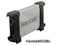
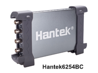
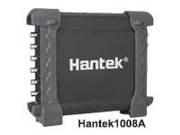
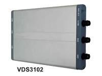
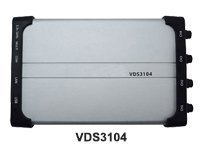
PC Based Oscilloscopes
PC based oscilloscopes are the modern alternative to the traditional bench top oscilloscope. All data and configurations measured on these oscilloscopes can be saved into a PC for further data analysis.
One of the key factors involved is the USB connection. The USB (universal serial bus) is intended for communications between interfaces, such as the oscilloscope and the PC in this instance.
PC based oscilloscopes come in either internal or external versions.
The external version(s) is a small unit that connects to a PC, usually by a USB. They can be used by a laptop or a desktop computer.
The internal version(s) usually come with a plug in card that is PCI format. This does not allow for portability and being that the card is placed in the actual PC, there is a lot of noise which could interfere with the results that are being measured.
 |
 |
 |
 |
 |
 |
Advantages of PC Based Oscilloscopes:
Easy to Use
Portable
Cost Effective
Large Display
Uses already "off-the-shelf" equipment- USB and PC
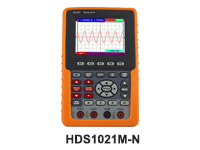
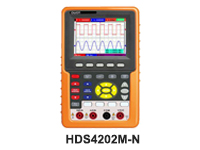
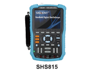
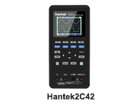
Portable Oscilloscopes
Portable Oscilloscopes are otherwise known as handheld oscilloscopes. They are typically used for on site contractor maintenance and either in the industrial or electronic field.
If you need to move your oscilloscope around to many locations or from bench to bench in your lab, then the portable oscilloscope would be ideal for you.
 |
 |
 |
 |
 |
.jpg) |
 |
 |
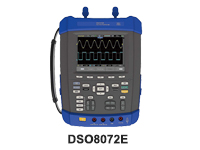 |
Advantages of a Portable Oscilloscope
Lightweight
Easy to Use
Turn On and Off Quickly
Please only acknowledge our contact email as sales@wellzion.com.
Recently the email server in risk of virus attack!